| |
||
A
rheometer is an instrument for measuring the flow and shear deformation
of materials. The two most widely used laboratory methods of determining
rheological data are Capillary Rheometers
and Rotational Rheometers.
Choosing which piece of equipment to use for a specific application
can be simplified by asking the question "Are
we interested in material behaviour under simulated processing conditions
or discriminating structural differences in compared samples?".
A Capillary Rheometer is best suited to the measurement of shear viscosity
at process-relevant shear rates, extensional viscosity & pressure
dependent viscosity, whereas rotational rheometry is most suited to
very low shear rate / viscosity measurement, determining changes in
structural properties via low amplitude, controlled strain oscillatory
measurements and associated tests such as yield stress analysis &
creep / creep recovery. |
||
A
capillary rheometer (Figure 1) is basically a highly instrumented,
accurately controlled, ram extruder. The most common configuration is
that of a vertically mounted heated barrel containing a capillary
die of known, accurately measured, L/D ratio. Above the die entrance
situated in the barrel wall is a pressure transducer. A closely
fitting piston is driven into the barrel at exactly controlled
constant speeds and a pressure drop generated at the capillary die.
This pressure drop is allowed to stabilize at which point readings of
piston speed and pressure are taken. The speed is then increased to
the next pre-determined point and the stabilization sequence repeated.
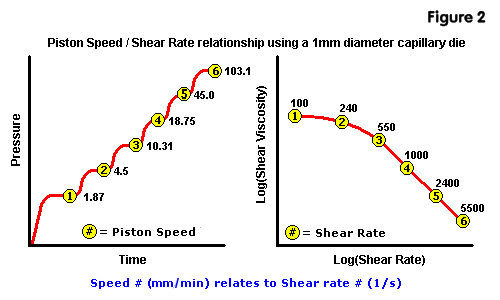
To obtain shear viscosity Vs shear rate
curves, a family of speeds / pressure drops are generated (speed dependent
on required shear rates and capillary die diameter - Figure 2).
|
Figure
1 Schematic of a Capillary Rheometer in Operation  |
 |
Measurements
are normally made using two capillary dies - one long die (usually
~20:1 L/D ratio) and a short die (~1:1 L/D ratio). This enables the
use of the Bagley end correction
formula. The overall pressure drop through a die consists of an entrance
pressure, pressure drop along the capillary length (land), and a small
exit pressure. The Bagley code removes the entrance & exit pressure
effects, the corrected pressure therefore relating to steady state
pressure flow within the capillary only. The formula assumes that
for the same rate of flow Q, the
entrance and exit pressure drops for two dies of the same diameter
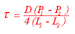
but different lengths are the same. Instead of calculating shear stress,
t, using the formula: |
 |
| Where D is the capillary diameter, L the length and P pressure, the difference in pressures between the long and short dies is employed: |
 |
| For the processing calculations used in injection moulding flow simulation packages, corrected data is essential since flow channels can be long, continuous, and thin. Uncorrected viscosities measured on a single capillary die would over estimate the pressure drop and therefore the viscosity. |
| The rheometer can cover a wide shear rate range, for example, with a 1mm diameter capillary die a range of ~1 to 50,000 1/s can be achieved. Higher or lower ranges can be achieved by altering the die diameter - doubling the diameter reduces the shear rate range by a factor of 8, conversely halving the diameter increases the range by a factor of 8. The shear stress is also related to the die geometry - doubling the capillary length halves the shear stress and so on. The capillary rheometer is also used for other applications such as the determination of Slippage, Extensional Viscosity & hydrostatic pressure effects on viscosity. |
A
controlled stress rotational rheometer is an extremely sensitive,
yet robust bench top instrument which is available in a number of
machine configurations. The business end of the rheometer consists
of a range of modular measurement systems comprising of either cone
& plate, plate / plate or coaxial cylinder configurations (Figures
3a, 3b & 3c). Measurement geometries are connected to
a spindle which is driven via a non contact induction motor. The drive
system is supported by a high quality porous carbon air bearing which
results in virtually frictionless movement of the measurement system.
Angular deflection is detected via a low inertia optical encoder to
high accuracy. Temperature of the sample is controlled by an environment
controlled heated clamshell oven & baseplate. |
Figure
3a - Cone & Plate |
Figure
3b - Plate / Plate |
Figure
3c - Coaxial Cylinder |
 |
 |
 |
| Measurement
Techniques |
|
|
 |
 |
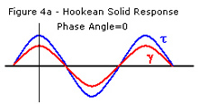
| Measurements are made over a range of frequencies and a family of curves generated. Data of most interest derived from these oscillation strain control measurements are Complex Viscosity (h*), Phase angle (°), and Storage and Loss modulus (G' & G"), as a function of frequency, (Figure 5). |
|
|
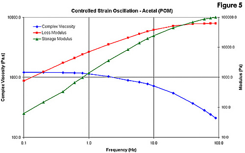
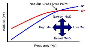
| The limiting (plateau) viscosity reached at low frequency is indicative of a material's zero shear viscosity and therefore it's molecular weight. The point at which the G' & G" curves cross over can also be a good indication of magnitude of molecular weight and molecular weight distribution, (Figures 6a & 6b). The relationship of G' to G" describes the visco-elastic response of the material. Phase angle or Tan phase (Tan Delta) is a good indicator of phase transitions (e.g. Tg) when measurements are made as a function of temperature. |
| Figure
6a |
Figure
6b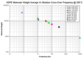 |
| For these reasons the measurement is ideal for detecting discrete changes in sample structure and can be used for discriminating batch to batch variance in pre-process QC testing of bought-in materials, degradation of materials during processing resulting in chain scission / cross linking and failures in service due to e.g. UV / thermal / chemical degradation. Materials which cannot be dissolved to enable molecular characterisation by Gas Permeability Chromatography (GPC) such as Acetal (POM) & ECTFE can also be easily characterised using oscillatory rheometry. |